Chief Scientist
Dong-Lin Li
Plan
In order to achieve real-time underwater data transmission, we conduct research and development on three important issues.
(A) Building an Effective Sonar Transmission System.
(B) Enhancing channel transmission capacity through encoding.
(C) Increase the battery discharge at low temperature effectiveness.
(A) Building an Effective Sonar Transmission System
Considering the characteristics of the marine environment and acoustic transmission in the surrounding waters of Taiwan, in this project, we aim to develop an autonomous underwater acoustic communication sonar system, which includes an electronic system, a pressure-resistant watertight capsule, and a fixed outer frame. The watertight capsule contains a power supply module, core control module, and signal amplification and conversion module for the entire system. The outer part of the watertight capsule is connected to a high-power intermediate frequency (IF) sound probe and microphone with a pressure-resistant watertight connector. The core control module is used for controlling the generation, transmission, reception, demodulation, and storage of signals in underwater communication. Fig. 1 shows an exploded-view drawing of the internal structure of the watertight capsule of the sonar system. The interior of the capsule consists of a core control module, digital amplifier, lithium battery, transformer circuit, and power management module. When the system is in operation, it is difficult to dissipate heat in the watertight capsule, and all the circuits in the capsule are thermally conductive. Metal has better thermal conductivity than gas. Hence, the excess heat generated by the system is diverted from the metal heat conductor to the end caps of the watertight capsule to prevent the system from overheating.
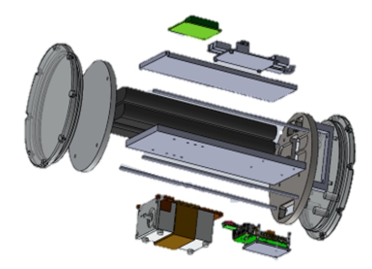
Fig. 2 presents the schematic diagram of the designed underwater sonar system. The transmitter comprises the data to be transmitted, source encoding, channel encoding, and a modulator. The transmitter will be programmed in Python by considering the relatively low requirements for data transmission speed underwater and characteristics of long-distance communication. The required hardware includes a single-board computer, an analog-to-digital converter (ADC), and a digital-to-analog converter (DAC) to drive the sonar transmitter and receive data from the hydrophone.
The receiver involves signal reconstruction, a demodulator, channel decoding, source decoding, and data recovery. Similar to the transmitter, the entire demodulation module of the receiver is also written in Python, thereby archiving the functions of the transmitter and receiver. The demodulation is performed by a single-board computer with ADC and DAC chips as opposed to via hardware implementation. Real-time changes to the parameters of the receiver and changes to the modulation method can be performed via programming. Hence, data can be sent and received via the underwater channel.
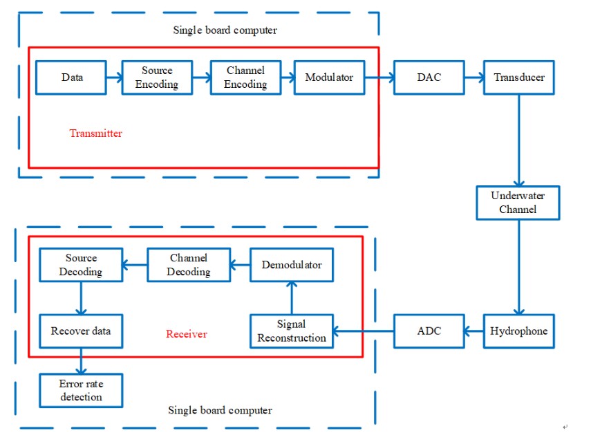
The design for the second year requires transmission over longer distances and to a depth of 200 m on the seabed. Hence, we use an adaptive filter to restore the signal after waveform reconstruction to reduce the issues associated with multipath propagation.
The Year-3 design continues the first year’s design, but the aim is to realize signal transmission over longer distances. Hence, the adaptive filter at the receiver side is replaced by an equalizer to compensate for the signal fading caused during transmission to reduce the signal distortion due to long-distance transmission.
Last year, we will adopt artificial intelligence (AI) for demodulation, and channel encoding will be removed to improve bandwidth utilization. By removing channel encoding, the transmitter includes only the source encoder and modulator for sending signals. This in turn can significantly increase the transmission rate. On the receiver side, the acoustic signals are quantized and reconstructed by the ADC, and then the signals are passed to an AI module for bit recognition. Specifically, the AI module replaces the demodulator and channel encoding module that have been used in the first three years of design. It is expected that the data transmission rate can be increased by using the AI-based receiver, and the error rate can be significantly reduced to optimize bandwidth utilization.Below are our annual goals for this sub-project:
- Year 1
- To realize communication within a range of up to tens of meters with a transmission rate of 1 kbps and BER of 10-5.
- Year 2
- To realize communication within a range of up to hundreds of meters with a transmission rate of 1 kbps and BER of 10-5.
- Year 3
- To realize communication within a range of up to 1 km with a transmission rate of 1 kbps and BER of 10-5.
- Year 4
- To realize communication within a range of up to 1 km with a transmission rate of 1 kbps and BER of 10-5.
(B) Enhancing channel transmission capacity through encoding
Considering Thorp’s underwater channel model, the most widely used model for underwater communication, we first investigate its outage channel capacity under different distance, signal frequency, and spreading factor. The outage capacity can be viewed as an approximation of the largest reliable transmission rate between two terminals. By varying the spreading factor, the outage capacity for shallow water or deep water can be obtained, allowing us to characterize a fundamental limit for various UAC. For the case of multiple terminals, the average outage capacity of the overall network will be formulated, and numerical results will be examined to find the optimal geometric distribution of underwater instruments which can maximize average outage capacity.
For reliable communication, we plan to adopt a special form of sparse code multiple access (CSMA), which combines the advantages of orthogonal-frequency-division-multiplexing (OFDM) and code division multiple access (CDMA). Note that to mitigate the long propagation delay problem, the OFDM systems need to operate in a low data rate; by contrast, the CDMA systems require a background control information exchange, which reduces the data transmission rates. The idea of CSMA was recently developed for RF channels, and the use of this technique for UACs is still lacking. Via computer simulations, we first evaluate the end-to-end bit-error-rate (BER) achieved by conventional CSMA schemes. Then, we optimize the CSMA based on an error rate analysis and information-theoretic measure. Another direction to boost the system performance can be borrowed from intelligent reflecting surface (IRS) for RF channels, which can reflect the non-light-of-sight signal wave to the desired position. Furthermore, instead of against multi-path, we design transmitted signals so that the superimposed signal due to the multi-path can be viewed as a Markov encoding process. In other words, the multi-path effect is regarded as a coding process. The viewpoint turns inter-symbol interference into a coding gain; the complexity of the encoding is also reduced, thus saving the power consumption at transmitters.
There are other essential building blocks for real system operation, such as frame detection, timing/frequency synchronizations, channel estimation, and channel equalization. The frame structure of the transmission signal plays an important role for success detection and synchronization (system access). Due to the double dispersion property in underwater acoustic channels, the conventional preamble or pilot sequence design may not be suitable for the use in UAC network, and the delay correlator may not be optimal. Given Thorp’s channel model, we explore preamble and pilot sequences which can maximize the success rate via a computer search. An algebraic design will be also developed to combined the above CSMA scheme. The detection and synchronization method as well as channel estimation will be jointly considered in the design of frame structure.
With the above obtained results, our next step is to construct a complete communication system by developing a computer simulation platform for verification and demonstration. A software-defined-radio underwater acoustic modem is planned to be implemented on a digital signal processing board and tested in laboratory and in open water. Fig. 3 is the focus for this sub-project. Below are our annual goals for this sub-project:
- Year 1
- Channel capacity analysis for underwater acoustic channels and finding the fundamental limits for transmitting data in UAC under various conditions.
- Year 2
- Designing transmission schemes and coding system for reliable UAC, including data compression/data protection/signal modulation.
- Year 3
- Designing system access procedure, algorithm, and protocol. Constructing a simulation platform on computers.
- Year 4
- Implementing a software-defined-radio underwater acoustic modem.

(C) Increase the battery discharge at low temperature effectiveness
There are many studies related Lithium-ion battery especially for low temperature operation. With low temperatures and high charging rates, the serious problems of lithium plating on the anode surface and unstable solid–electrolyte interphase (SEI) are reported in Gao et al. (2020) and Yang et al. (2018). Battery models are widely investigated so that the appropriate charging method is designed (Tippmann et al., 2014; Suthar et al., 2015). For example, in Suthar et al. (2015), an electrochemical engineering model is utilized and dynamic optimization framework was applied to derive charging profiles to minimize lithium plating at low temperatures.
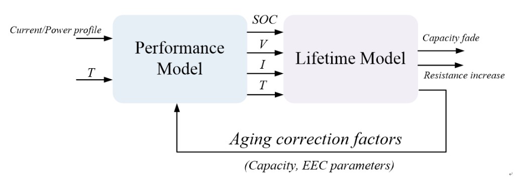
Fig. 4 shows the block diagram of battery modeling comprised of performance model and degradation model. The performance model takes current profile and temperature as inputs, and output the instantaneous voltage response and SOC. On the other hand, with the SOC, voltage/current profile and temperature obtained from performance model, degradation model enables to show the degree of capacity reduction and the increment on internal resistance due to aging. The aging effect obtained from the degradation model will feedback to the performance model to update the parameters of the equivalent circuit, i.e. capacity and resistance. The modeling of the battery cell is based on second-order RC Thevenin equivalent circuit model, namely 2RC model. The circuit parameters of the 2RC model can be expressed as the functions of influential factors including temperature, SOC, current and aging effect (Stroe, 2014). To formulate the function of the circuit parameters in terms of influential factors, it is required to learn the relationship between the influential factors and the circuit parameters through a series of experiments. After obtaining the measured data, optimization method is applied to minimize the error between the simulated result from the cell model and the measurement data. In this way, the parameters of battery model are able to be adjusted to meet the behavior of the real one.
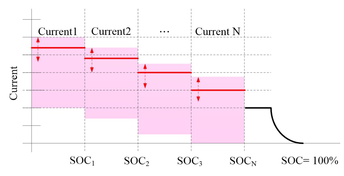
With the battery cell model, the design and evaluation of the charging methods has become more efficient and time-saving. In fact, the charging method has a direct impact on the performance and lifetime of lithium-ion battery. Taking the traditional constant current and constant voltage (CC-CV) charging method as an example, although CC-CV method is simple to implement, relatively long charging time may reduce the life cycles of battery cell. On the other hand, despite the fact that the multi-stage constant current method has the advantages of higher charging efficiency, shorter charging time and longer cycle life, it is difficult to determine the optimal charging current for each stage due to the complex electrochemical characteristics. Therefore, in order to determine an appropriate charging current for different levels of SOC and improve the battery lifetime, this project in the third year aims to design the optimum charging method particularly considering the low environment temperature. A conceptual figure is given in Fig. 5.
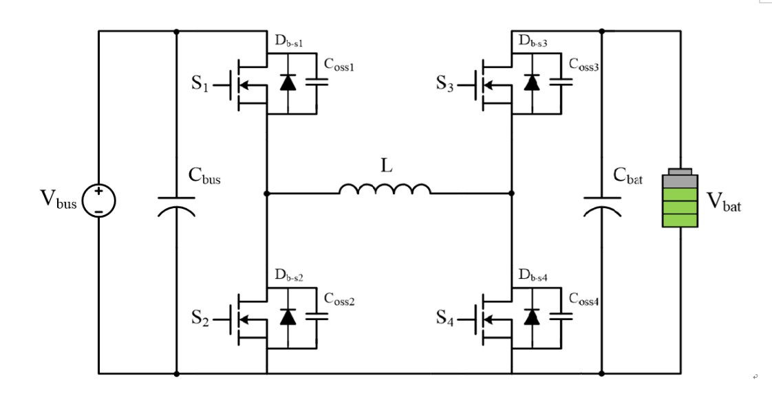
Since the power transfer between the battery pack and instrument load relies on a high-efficiency power converter, this sub-project plans to realize a bidirectional buck-boost DC-DC converter and implement the proposed optimum charging method. Fig. 6 shows the circuit diagram of the bidirectional buck-boost DC-DC converter. The terminal voltage of battery pack will determine the mode in which the bidirectional buck-boost DC-DC converter operates. During charging, if the battery terminal voltage is lower than the bus terminal voltage, the bidirectional buck-boost DC-DC converter will operate at buck charging mode; otherwise, it operates at boost charging mode. During discharging, if the battery terminal voltage is lower than the bus terminal voltage, the bidirectional buck-boost DC-DC converter will operate at boost discharge mode; otherwise, it operates at buck discharge mode. Below are our annual goals for this sub-project:
- Year 1
- Development of battery performance model.
- Year 2
- Development of battery aging model.
- Year 3
- Design of optimum charging strategy for low operating temperature.
- Year 4
- High efficiency bidirectional buck-boost DC/DC converter.
